
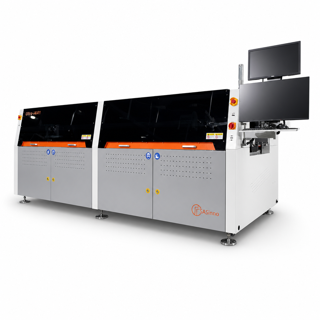
Ultra-i4/41 – Inline selective soldering systemInline · Selective soldering

Inline selective soldering system

Ultra-i4/41

Four pumps. One clear production flow.

The Ultra-i4/41 is designed for inline selective soldering. Four electromagnetic pumps and software-controlled axes support series production.

Understand selective soldering ↗

600 × 600mm PCB format
4 electromagnetic pumps · 1 drop-jet fluxerRequest a system

The equipment makes
the difference.

Ultra-i4/41: Technology and functions for your manufacturing process.

Standard equipment

10 features

4 electromagnetic pumps

4 solder pots with electromagnetic pump technology direct solder precisely to the solder joints.

1 drop-jet fluxer

Flux is applied precisely by a drop-jet fluxer. The fluxer is cleaned automatically.

Top and bottom preheating

A preheating zone with top convection and bottom infrared prepares the assembly. An additional IR heater acts above the soldering area.

4 inline nitrogen heaters

The integrated nitrogen heating supports the process atmosphere in the soldering area.

Automatic wave-height calibration

The system calibrates solder-wave height automatically.

Fiducial recognition and board scan

The standard camera detects fiducials and supports PCB capture.

Live camera for the soldering process

The soldering operation can be monitored on screen during operation.

Servo drives on all motion axes

All motion axes are driven by servo motors.

Smart Soldering software

Solder points and travel paths are programmed in SASinno software. The user interface runs in English on Windows 11.

Software-adjustable solder pots

Four Z axes, four X axes and two Y axes enable software-controlled adjustment of the four pumps.

Options & configuration

1 feature

Alternative power supply

A three-phase 220 V version is available as an alternative to the 380 V supply.

Equipment according to the manufacturer description. Optional additions are listed separately; the specific configuration is defined in the quotation.

The facts.
At a glance.

Technical specifications are based on manufacturer information. We will agree the specific configuration with you.

Single PCB
50 × 50 to 600 × 600 mm
Four PCBs
Up to 370 × 320 mm each
Electromagnetic pumps
4
Nitrogen consumption
6 m³/h
Dimensions (L × W × H)
3,804 × 2,050 × 1,477 mm
Operating / maximum power
6 / 46 kW

Assess application and integration.

Ultra-i4/41: The system targets defined through-hole solder joints. PCB format, access and the thermal behaviour of the actual assembly determine the setup.

Application

Check joint locations, component clearances, nozzle access and heat demand on a sample assembly.

Line integration

Confirm fixturing or conveyor flow, line direction and height, plus the utilities and interfaces of the ordered configuration.

Limits and trial

An admissible PCB format alone does not prove solderability or throughput. Check wetting, thermal profile and component limits in a soldering trial.

More details for your planning.

You can obtain manuals, equipment details and project-specific information directly from our team.

Request documentation

Knowledge from practice

What prepares a good solder joint.

Fluxing, preheating and soldering: learn about the three process steps and their key influencing factors.

Read the article

Your assembly.
Our next conversation.

Let’s discuss which solution suits your process.

Contact