
Process · Automated Dispensing
Dispensing systems for electronics manufacturing
Automated dispensing systems apply material repeatedly at programmed positions. In electronics production, material properties, required geometry, deposit volume, valve, needle and process control determine the result together.
How automated dispensing works.
A motion program guides the dispensing head along defined points and paths. The SD-400i supports points, lines, circles and rectangles. A CCD camera assists teaching and positioning.
After a needle change, needle alignment and Z height can be calibrated automatically. This supports setup, but actual dispensing quality still needs to be confirmed using the real material and a sample assembly.
Typical dispensing tasks.
Dots and defined volumes
Material is applied at specified positions when location and volume are critical to the function.
Lines and contours
Programmable paths support continuous deposits along defined geometries.
Different materials
Depending on valve and material data, different tasks can be evaluated. Actual compatibility is defined for each project.
From material to a stable deposit.
1. Characterise material
Viscosity, fillers, pot life, temperature behaviour and curing affect the valve and process settings.
2. Program geometry
Position, paths, clearances, needle height and deposit volume are configured on the actual assembly.
3. Calibrate and inspect
Needle and Z height are set. Samples show whether shape, volume and repeatability meet the requirement.
Selection criteria for a dispensing system.
Material and valve principle
Flow behaviour, particles, fillers and required volume determine which precision valve suits the task.
Dispensing area and component height
PCB, panel, fixture and tallest components must fit within the available working space.
Deposit geometry
Dots, lines, circles and contours place different demands on speed, distance and material flow.
Process environment and limits.
Material supply
Container, compressed air, degassing and refill concept influence process stability and operation.
Downstream steps
Curing, transport and inspection need to fit the dispensing process in time and space.
Sample trial
Positioning accuracy and working speed alone do not guarantee a suitable deposit. Validate the result using original material.
SD-400i example system
Verified key data.
These values describe the SD-400i. Valve, needle and process settings are selected for the material and dispensing task.
- Dispensing area
- 350 × 300 mm
- Axes
- X / Y / Z
- Working speed
- Up to 500 mm/s
- Positioning accuracy
- ± 0.05 mm
- Repeatability
- ± 0.05 mm
- Programming
- Camera-based teaching
Matching system.
View all technical data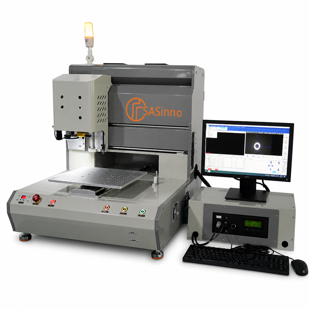
SD-400i
Compact benchtop dispensing system with servo axes, CCD positioning and automatic needle calibration.
350 × 300 mm dispensing areaOfflineInformation needed for system planning.
Useful inputs include the material and safety data sheets, target volume and geometry, PCB size, component heights, fixture, cycle-time requirement, curing and quality-inspection information.
Why a dispensing trial is necessary.
Viscosity, temperature, needle, valve, distance and speed affect the result. A test with original material and the actual assembly shows whether the required shape and volume can be achieved consistently.
Frequently asked questions about automated dispensing.
Which geometries can the SD-400i program?
The manufacturer information lists points, lines, circles and rectangles as well as position correction.
Which dispensing valve is required?
This depends on material, viscosity, fillers, required volume and geometry. The system is compatible with different precision dispensing valves.
What is calibrated after a needle change?
The SD-400i supports automatic needle alignment and Z-height calibration.
Run a dispensing trial.
Send us material data, target geometry, assembly and required cycle time.