
Process · Conformal Coating
Selective conformal coating systems for PCB assemblies
Selective conformal coating systems apply coating material to defined areas of electronic assemblies. Programmed paths and suitable valves help cover target zones while accounting for connectors, contacts, test points and other keep-out areas.
Conformal coating in electronics manufacturing.
Conformal coating follows the contours of an assembled PCB and applies material to the intended areas. The protection achieved depends on the selected material, coating build and complete process, so the application system must be matched to the assembly and process objective.
SASinno develops benchtop and inline systems for selective application. SASinno Europe supports system selection, sample evaluation and integration planning for European production environments.
What “selective” means
The program defines travel paths, valve states and coating zones. Areas that must remain free are considered during programming, fixturing and sample evaluation, allowing the process to follow the actual assembly geometry.
The process in three stages
First, the assembly, coating zones and keep-out areas are recorded. The selected valve then applies material along programmed paths. Finally, the result is inspected; drying or curing must be planned around the selected coating material and production concept.
Which machine format fits?
PCB format and component height
Check the usable coating area, actual workpiece or carrier dimensions and component heights on both sides. For systems with two work platforms, the specified coating area applies to each platform.
Benchtop or inline
A benchtop system is loaded and unloaded as a stand-alone cell. An inline system also requires coordinated conveyor direction, transport height, width adjustment and interfaces to adjacent equipment.
Valves and coating pattern
Narrow spray and needle valves are standard on the listed SASinno models. Film and wide spray valves are model-dependent options. Selection depends on material, surface area, contours and the required application pattern.
Keep-out zones and programming
Connectors, contact areas, test points and other restricted zones must be checked in the program and on the actual sample assembly. CCD-assisted teaching plus DXF or image data support setup.
Utilities and production environment
Material supply, cleaning medium, compressed air, extraction and, for inline systems, line interfaces all belong in the project definition. Required values are confirmed for the chosen machine and material.
Match the material and application process.
A coating program alone does not determine a reliable result. Viscosity, valve type, flow, travel speed, distance to the assembly and geometry interact. The process should therefore be evaluated with the intended material and a representative sample assembly.
Standard equipment and options
The SC-902 is described with a narrow spray valve and needle valve. The SC-903R and SC-904 also use different precision valves; the SC-904 carries four standard valves. Material weighing, vacuum tank mixing, barcode reading and film or wide spray valves are listed as model-dependent options. The agreed configuration is decisive.
Inspection after application
The coating should be assessed against the defined zones and defect criteria. The separate coating inspection process can be added for automatic inspection; line integration is planned for the project.
Limits and open project questions.
Material approval
Material compatibility, viscosity window, cleaning and curing must be aligned with the selected coating and the assembly requirements.
Complex shadow areas
Tall components, narrow spaces and concealed surfaces can limit access. A sample coating shows whether valve, angle and travel path reach the target zone reliably.
Very small dispensing points
For dots or beads of adhesive, encapsulant or other materials, a dispensing system may fit better. Coating and dispensing should be assessed separately according to material and target geometry.
Downstream process
The systems described here apply material. Drying, curing, inspection and traceability requirements must be considered across the complete production flow.
Matching systems.
Compare systems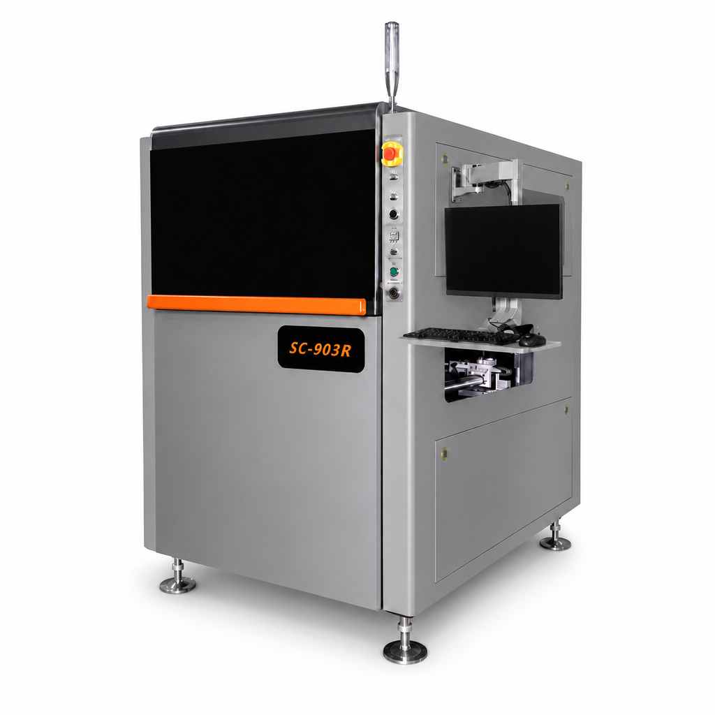
SC-903R
The SC-903R combines servo-controlled X, Y, Z and R axes with flexible valve technology. The CCD camera supports programming and fiducial recognition.
500 × 500 mm maximum coating areaInline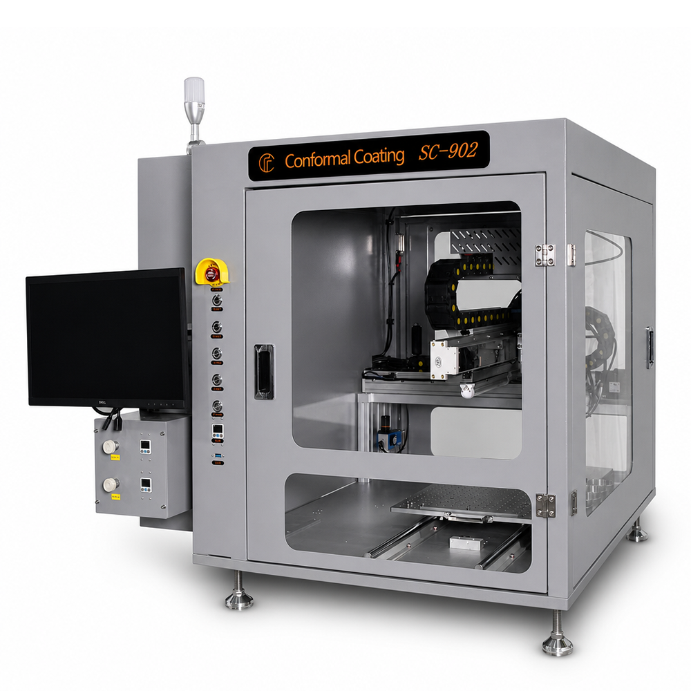
SC-902
Benchtop system with two platforms, CCD programming and two installable valves.
400 × 300 mm coating area per platformOffline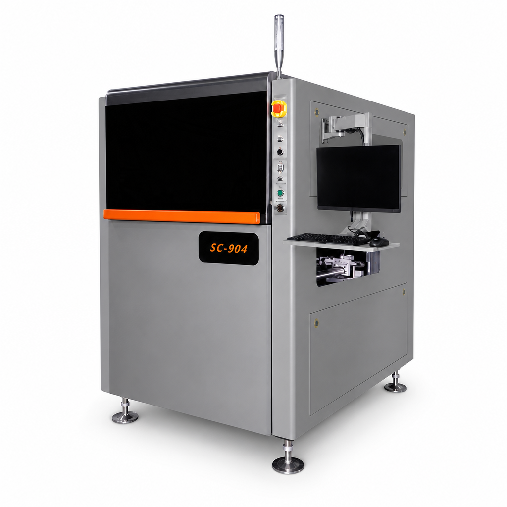
SC-904
Inline coating system with four valves and motorized width adjustment.
260 × 480 mm coating area per PCBInlineThese details speed up system definition.
A reliable initial selection starts with the actual assembly and intended material. Photos or layout data help, but they do not replace evaluation of a representative populated board.
For a sample coating
Prepare PCBs or carriers, coating material and a clear map of target and keep-out zones. Also state how the applied coating should be assessed.
Important project data.
Assembly
Dimensions, carrier format, component heights, overhangs and sensitive areas.
Material and process objective
Material designation, viscosity or processing window, target zones and the intended protective function.
Line integration
Benchtop or inline, conveyor direction, transport height, interfaces, extraction and required traceability.
Frequently asked questions about conformal coating systems.
What is a conformal coating system?
It applies coating material to electronic assemblies. A selective system follows programmed target areas while defined keep-out zones are intended to remain free.
Which data determines machine selection?
PCB or carrier format, component heights, coating material, target zones, keep-out areas, required valves and the planned benchtop or inline integration.
When does a benchtop system fit?
A benchtop system can suit stand-alone cells, samples and applications with manual loading. Suitability depends on format, process time and production flow.
Are all valve types standard?
No. Narrow spray and needle valves are standard on the described models; additional valve types are listed as model-dependent options. The specific quotation defines the configuration.
Is coating inspection integrated?
The CI-900 is a separate inspection system. The connection between application, drying and inspection is defined for the line project.
Related processes.
Coating inspection ↗
See how applied conformal coating can be inspected optically in a separate process step.
Dispensing ↗
Distinguish area coating from dot or bead dispensing according to material and target geometry.
Your coating process begins
with material and assembly.
Send us the format, coating zones, material and production integration details.