
Process · Wave Soldering
Wave soldering systems for THT series production
SASinno wave soldering systems combine flux application, configured preheating and two solder waves for continuous THT production with 350, 450 or 600 mm conveyor width.
Wave soldering for repeatable THT series production.
Wave soldering systems guide a populated PCB through flux application, preheating and one or more solder waves. Many suitable THT joints can be processed in a continuous production flow. Layout, component arrangement, solder frame or carrier, thermal limits and the process window must match the application.
SASinno develops the iWA series for different conveyor widths and thermal requirements. SASinno Europe supports system selection, sample evaluation, commissioning and operator training.
The three core process steps
The spray fluxer applies flux to the solder side. Preheating prepares the PCB, components and flux for contact with the solder. In the soldering module, the conveyor moves the assembly over the solder waves. Conveyor speed, preheating and soldering parameters are set for the actual assembly.
Which iWA configuration fits?
350 mm conveyor width
The iWA-350S is the compact version of the series. It combines a spray fluxer, convection preheating and two solder waves.
450 mm conveyor width
The iWA-450 and iWA-3-45 process PCBs or carriers up to 450 mm wide. Their preheating configurations differ.
600 mm conveyor width
The iWA-600 and iWA-3-60 are designed for larger formats up to 600 mm conveyor width. Floor space, thermal profile and line layout must be checked in addition to format.
Equipment and options
Nitrogen protection, inline heating and automatic solder-bar feeding are available as model-dependent options. They should only be included after the required configuration has been confirmed.
System planning
From the assembly to the right wave soldering system.
Format, carrier and conveyor
The decisive dimension is the total transported width, including production panel, solder frame or workpiece carrier. Conveyor direction, transport height, PCB length, component overhang and transfer to adjacent equipment are also required.
Thermal demand
PCB thickness, copper content, component mass and permitted component temperatures influence the required preheating. iWA models differ in the number and type of preheating zones. A measured profile on a sample assembly provides the reliable basis.
Layout and process access
Component spacing, shadow areas, solder masking and access to THT terminals influence wave-soldering suitability. Solder, flux and quality requirements must be evaluated together.
When selective soldering should be evaluated
If only a few THT joints need soldering, sensitive areas should remain outside solder contact, or the product mix changes frequently, selective soldering may fit better. The decision should be based on assembly, target process and production volume. Our selective and wave soldering guide summarises the main differences.
Matching systems.
Compare systems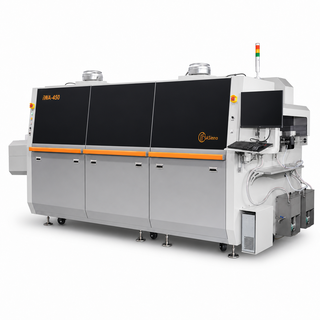
iWA-450
The iWA-450 is a lead-free wave soldering system for THT assemblies. It processes PCBs up to 450 mm wide with two solder waves.
450 mm maximum transport widthInline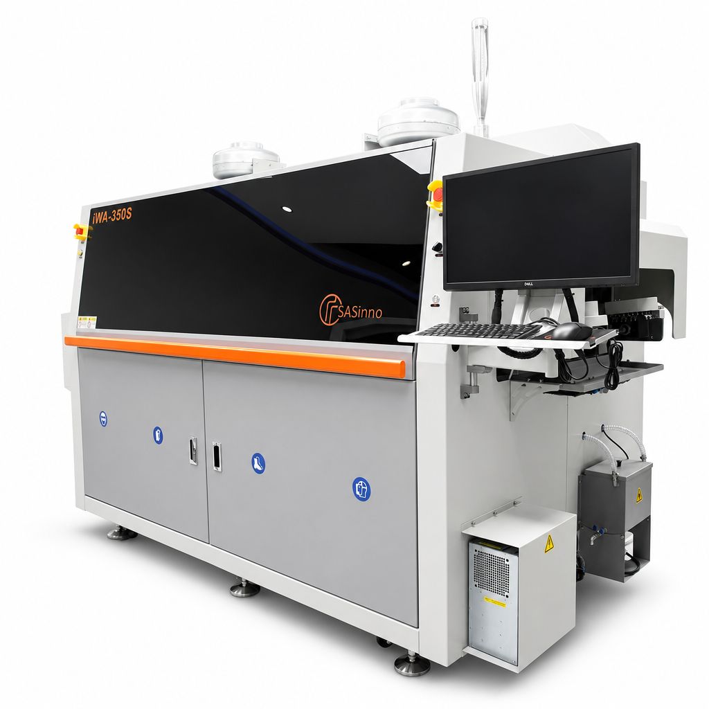
iWA-350S
Wave soldering system with spray fluxer, convection preheating and two solder waves.
350 mm maximum transport widthInline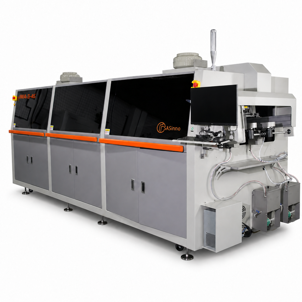
iWA-3-45
System with spray fluxer, convection, IR preheating and two solder waves.
450 mm maximum transport widthInline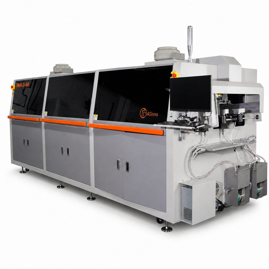
iWA-3-60
Inline wave soldering system with two solder waves plus hot-air and IR preheating.
600 mm maximum transport widthInline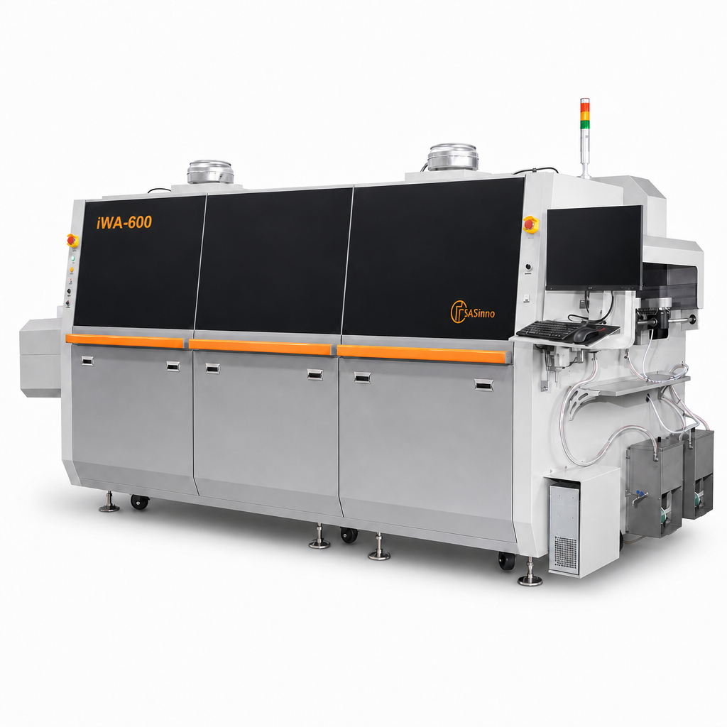
iWA-600
Inline system with two solder waves and selective spray fluxing for PCBs up to 600 mm.
600 mm maximum transport widthInlineFrequently asked questions about wave soldering systems.
Which assemblies are suitable for wave soldering?
Typical applications are THT assemblies where many suitable joints can be processed in a continuous flow. Layout, component spacing, masking and thermal limits must fit the wave-soldering process.
What distinguishes selective from wave soldering?
Selective soldering processes defined joints locally. In wave soldering, the assembly passes over a continuous solder wave. Assembly layout, volume and process objectives determine the better fit.
Which width should be specified?
The total width of the transported PCB or carrier, not only the usable area of the populated board. Component overhang and necessary edge areas must also be included.
What information is needed for system planning?
PCB and carrier format, populated side, THT layout, thermally critical components, solder and flux, target volume, line direction and transport height, plus sample assemblies for process evaluation.
Which equipment is optional?
Nitrogen protection, inline heating and automatic solder-bar feeding are listed as options depending on the iWA model. The agreed quotation defines the binding configuration.
Your process begins
with your assembly.
Tell us the format, application and desired production integration.